Equipment
Special adapted options for Visatron Oil Mist Detector – to optimize your system!
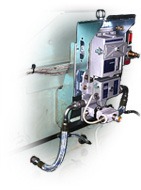
Engine Protection Partner AS is your best partner for complete installations of oil mist detection systems.
We require no specification drawings of the engine- only images and information about engine wall dimensions. The brackets and bending of the tube takes place on the instalation site. Our Service Personnel are recognized worldwide for its on-site installations. All piping systems are delivered with long-type sampling funnels.
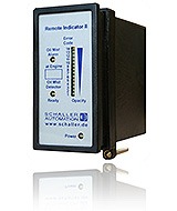
- Full overview of “real time” measurement of oil mist concentration
- Secures personnel’s situation in cases of high oil mist alarm
- Meet’s the IACS UR 10.11 requirement
- Easy to install
| Remote indicator unit II | Part no. 11506 |
| Connector FK-MCP 1,5/12-STF-3,81* | Part no. 11507 |
| Grommet | Part no. 11501 |
| Network terminator | Part no. 11502 |
| Front glass plate for horizontal installation | Part no. 11510 |
| Front glass plate for vertical installation | Part no. 11511 |
| Jumper | Part no. 11512 |
| 5 x label engine type | Part no. 11508 |
| Name: | Pin- no. Remote indicator II: | Connected to pin- no. on oil mist detector: | |
| RS485 A | 1 | Pin 13 of VN/93 and VN/87plus | |
| RS485 B | 2 | Pin 11 of VN/93 and VN/87plus | |
| RS485 GND | 3 | — | |
| Optional current interface + | 4 | — | |
| Optional current interface – | 5 | — | |
| VN/87- PWM interface + | 6 | — | |
| VN/87- PWM interface – | 7 | — | |
| 4- 20 mA Output + (max. 220 ohm) | 8 | Optional to alarm monitoring system | |
| 4- 20mA Output – | 9 | Optional to alarm monitoring system | |
| Earth | 10 | Earth & data cable shield | |
| Power supply GND | 11 | 0 Volts | |
| Power supply 24 Volts | 12 | +24 Volts DC |
| Name: | Pin- no. Remote indicator II: | Connected to pin- no. on oil mist detector: | |
| RS485 A | 1 | — | |
| RS485 B | 2 | — | |
| RS485 GND | 3 | — | |
| Optional current interface + | 4 | — | |
| Optional current interface – | 5 | — | |
| VN/87- PWM interface + | 6 | Pin 9 of VN/87 EMC | |
| VN/87- PWM interface – | 7 | PIN 10 of VN/87 EMC | |
| 4- 20 mA Output + (max. 220 ohm) | 8 | Optional to alarm monitoring system | |
| 4- 20mA Output – | 9 | Optional to alarm monitoring system | |
| Earth | 10 | Earth & data cable shield | |
| Power supply GND | 11 | 0 Volts | |
| Power supply 24 Volts | 12 | +24 Volts DC |
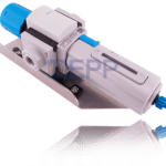
- The pressure reducer secures stabile and clean air to the oil mist detector
- Water/oil separator is included in the unit
- Filter element to supply clean air is included in the unit
- Solid construction with long life time
- Complete repair/ maintenance kit available
| Part no: | Product: | Additional information: |
| 273440 | Pressure regulator | Complete regulator |
| 100170 | Filter for pressure regulator | 1x Filter element kit 1x Quick guide |
| See product info | Part no.: 100168 – Pressure regulator Part no.: 100169 – Pressure regulator (opposite flow direction) | x1 Pressure regulator |
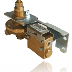
This product is out of production from 01.01.2020. Use your pressure regulator with part no.: 273440!
The Visatron pressure regulator is an important part combined with the oil mist detector. The device secures a safe operation of the airflow supplied to the oil mist detector. The system is build up with a safety unit that secures the airflow not to pass over max. 90,00 mm WC. The system also provides clean air to the oil mist detector threw the filter system. The pressure reducer is used for all VISATRON oil mist detectors.
Benefits:
- The pressure reducer secures stabile and clean air to the oil mist detector
- Air filter installed in the safety unit
- Solid construction with long life time
- Complete repair/ maintenance kit available
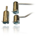
If there is too much oil in the oil mist detector and the pipe system, you need to check if there is sampling funnels installed in the crankshaft room on every suction point.
A sampling funnel is an oil labyrinth where the large oil droplets are filtered away, and just the small oil mist droplet will pass. It is necessary to install long type sampling funnels if the pipe system does not have the 2-4 % of an angel.
There is two different main types of sampling funnels: the short type (normally used for new engines) and long type sampling funnel (normally used for engines with age over 8 years). Please contact us for specified type for your engine!
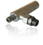

Oil draining device – Part no.: 11164
The oil draining device is used to drain back oil laying in the pipe system from the engine to the oil mist detector.
Oil separator – Part no.: 11163:
This oil separator unit drains / returns the oil coming out from the oil mist detector exhaust port. The oil separator unit is the solution to eliminate the problem with oil spills around the engine and to avoid that oil mist remains in the engine room atmosphere.
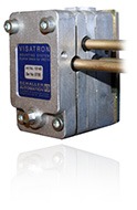
Not all engines allow installations where the main tube have recommended 2- 4 % angel. The reason why we recommend the 2- 4 % angel on the main tube is based that collected oil inside the tubing system are drained back to the crank case. The syphon blocks are specially made for oil mist detector installations where the main tubes are installed in horizontal position. The syphon blocks are designed to let the oil mist go through the pipe system and let the oil and oil droplets be drained back to the crank case. The design makes the installation of pipes quick and easy.
Benefits:
- Easy installation
- No need for main pipes system with 2- 4 % angel
- Easy to maintenance
Note:
The syphon block for the VN 215 series have different part numbers acc. to th eposition of the syphon block in the pipe system. Please see overwiev under for more information!
- Mounting plate
- Fastening screw for sampling funnel
- Syphon block body
- Suction tubes to the OMD device
Accessories:
| 1 | Syphon block VN 280 for 1 tube | Part no.: 10140 | |
| 1 | Syphon block VN 280 for 2 tubes | Part no.: 10142 | |
| 1 | Syphon block VN 280 for 3 tubes | Part no.: 10143 | |
| 1 | Syphon block VN 280 for 4 tubes | Part no.: 10144 | |
| 1 | Syphon block VN 280 for 5 tubes | Part no.: 10145 | |
| 2 | Mounting plate for syphon block | Part no.: 271544 | |
| 3 | O- ring set for siphon block VN280 | Part no.: contact us! | |
| 4 | Block plug for siphon block VN 280 | Part no.: 365287 |
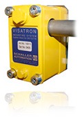
Not all engines allow installations where the main tube have recommended 2-4 % angel. The reason why we recommend the 2-4 % angel on the main tube is based that collected oil inside the tubing system are drained back to the crank case. The syphon blocks are specially made for oil mist detector installations where the main tubes are installed in horizontal position. The syphon blocks are designed to let the oil mist go through the pipe system and let the oil and oil droplets be drained back to the crank case. The design makes the installation of pipes quick and easy.
Benefits:
- Easy installation
- No need for main pipes system with 2- 4 % angel
- Easy to maintenance
Difference between VN 215 & VN 115/ VN 116 installation:
Accessories:
| 1 | Syphon block VN 180 | Part no.: 10013 | |
| 2 | Rubber insert for syphon block VN180 | Part no.: 10095 | |
| 3 | Mounting plate for syphon block VN180 | Part no. 10089 | |
| 4 | O- ring for siphon block VN 115 & VN 116 | Part no.: 365287 | |
| 5 | Plug for siphon block VN 180 | Part no.: 340375 |
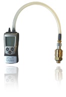
The digital u- tube manometer is easy to use for checking the negative pressure in your oil mist detector. The digital u- tube manometer shows the value in mmH2O- the same as mmWC. Recommended pressure is 60,00 mmWC/ mmH2O.
Benefits:
- Easy to use
- Do not require water to be filled in
- Solid construction with long life time
- Accurately and measuring
How to use:
- Before starting the procedure- stop the engine! Turn off the air pressure on the pressure regulator unit.
- Unscrew the plug (part no. 10083) on the inspection cover located on the measuring head. Install the quick connection (part no. 10053.),
- Press
 on the digital u- tube manometer- then 0,0 mmH2O will be indicated in the display.
 - Press in the main connection into the quick connection, and start to adjust the adjusting screw on the pressure reducer until the display show 60,00 mmH2O on the digital u- tube manometer.
- When this is done, disconnect the digital manometer from the oil mist detector- the negative pressure is now adjusted.
| Part no: | Product: | Other information: | |
| 100138 | Digital u- tube manometer | Complete manometer | |
| 10053 | Quick connection for u- tube manom. | Quick connection connected to inspection cover on OMD! | |
| 100139 | Adapter kit | Adapter connections incl. flexible pipe! | |
| 100140 | Batteries for digital u- tube manometer | 2 x 1.5 V AAA batteries. |
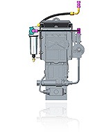
- For longer lasting fresh air filter/ scavenging air filter (P/n: 10042) lifetime
- Makes independ of onboard air quality
- Automatic de- oiling/ watering system as option
| Part no: | Product: | Other information: | |
| 272213 | Driving Air Conditioning Kit | Complete kit including point no.: 1,2, 4 & 5 | |
| 10753 | Protection cover | The driving air conditioning kit requires protection cover for installation. | |
| 10001 | Pressure reducer | The driving air conditioning kit requires pressure reducer for installation. |

 on the digital u- tube manometer- then 0,0 mmH2O will be indicated in the display.